NuCamRa
TM
Not your normal DSLR, Mirrorless or phone camera
Electronic Imaging Enhancement System
US Patent #11240451 granted February 1, 2022 by Craig T Cyphers
- No more catching as many photons as possible
- Now catch proportions of photons - 100% here, 3% there, 0.1% over there and 0.003% up there
- By adding neutral density type pixels to the color filter, of different values (ie. 7, 14 and 20 F-stops), to a third of the pixels on the normal Beyer color filter,
- Now you can record a picture with a 30 F-stop dynamic range.
——— But….., the real value ———
- When you make the sensor 1/4 the size and add 3 times as many pixels and you still have a sensor with 20+ F-stops dynamic range, more color information and 3 times as many pixels !!!
This patent will require many people to help it to come to fruition. I will need their help to just get it to a proper test and evaluation. I need to get this concept to as many decision makers inside the companies who design and manufacture photo sensors and color filters, as we possibly can. I hope to do this by following the logic of the game of “6 degrees of separation of Kevin Bacon”. This means that if would like to see these ideas implemented and you want to help in getting these goals achieved, please pass on a link to this website to those people you believe may know someone who may know someone like the people mentioned above, to get these concepts tested and evaluated. Thank you for any help that you can provide.
Game changing features
4 to 5 times more pixels
50 % more F-stops of Dynamic range
Smaller sensors
Smaller cameras
Smaller lenses
Lower cost
This web site will explain all of our new features, how they work, and why future upgrades will continue to make the cameras and lenses smaller, cheaper and better.
All of these improvements with just a newly patented color filter !!!


How It Works
How u can help
Goals
Why can u only

FAQ’s
Plan
Proof of Concept A
Proof of Concept B

Patent Explanation
Black Swan?
Glossary

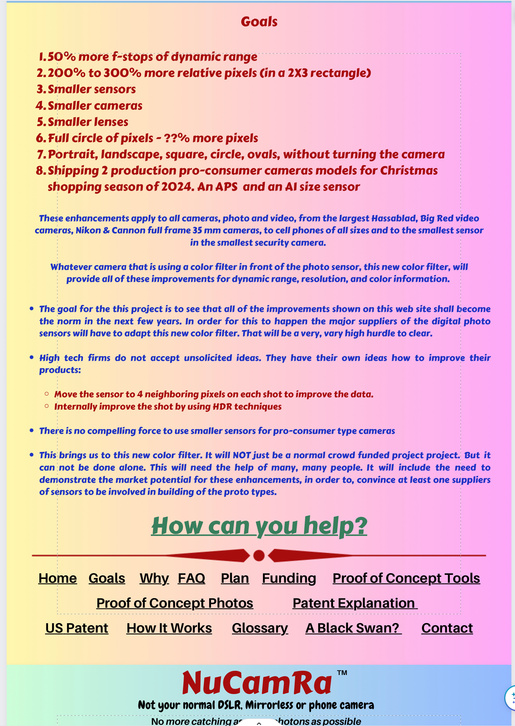
Goals
- 50% more f-stops of dynamic range
- 200% to 300% more relative pixels (in a 2X3 rectangle)
- Smaller sensors
- Smaller cameras
- Smaller lenses
- Full circle of pixels - ??% more pixels
- Portrait, landscape, square, circle, ovals, without turning the camera
- Shipping 2 production pro-consumer cameras models for Christmas shopping season of 2024. An APS and an A1 size sensor
These enhancements apply to all cameras, photo and video, from the largest Hassablad, Big Red video cameras, Nikon & Cannon full frame 35 mm cameras, to cell phones of all sizes and to the smallest sensor in the smallest security camera.
Whatever camera that is using a color filter in front of the photo sensor, this new color filter, will provide all of these improvements for dynamic range, resolution, and color information.
- The goal for the this project is to see that all of the improvements shown on this web site shall become the norm in the next few years. In order for this to happen the major suppliers of the digital photo sensors will have to adapt this new color filter. That will be a very, vary high hurdle to clear.
- High tech firms do not accept unsolicited ideas. They have their own ideas how to improve their products:
- Move the sensor to 4 neighboring pixels on each shot to improve the data.
- Internally improve the shot by using HDR techniques
- There is no compelling force to use smaller sensors for pro-consumer type cameras
- This brings us to this new color filter. It will NOT just be a normal crowd funded project project. But it can not be done alone. This will need the help of many, many people. It will include the need to demonstrate the market potential for these enhancements, in order to, convince at least one suppliers of sensors to be involved in building of the proto types.
NuCamRa
TM
Not your normal DSLR, Mirrorless or phone camera
No more catching as many photons as possible
Now catch proportions of photons - 100% here, 3% there, 0.1% over there and 0.003% up there
Why can you only
choose this
Or this?


When you can have both AND
All of these !!!


AND MORE !!!
With ONE shot, that records the light from the
full CIRCLE of the lense, not just a smaller rectangle.
and this is only the ONE of the
list of important new features
This web site will explain all of these new features, how they are done, and why future upgrades will continue to make the cameras and lenses smaller, cheaper and better.
Summary of changes in the same size sensor with shrinking pixel sizes and added neutral density types added to the filter
cells in repeating patteren | 4 (2X2) | 9 (3X3 | 16 (4X4) | 25 (5X5) | 36 (6X6) |
Repeating pattern sq area | 1 | 1 | 1 | 1 | 1 |
Pixel sq area | .25 | .11 | .0625 | .04 | .03125 |
Number of pixels per sensor | 12 M | 27 M | 48 M | 75 M | 108 M |
F-stops of dynamic range per pixel | 12 f-stops | 10 f-stops | 10 f-stops | 9 f-stops | 8 f-stops |
one 6 f-stop pixel per repeating pattern | 18 f-stops | 16 f-stops | 16 f-stops | 15 f-stops | 14 f-stops |
one 6 f-stop pixel & one 12f-stop pixel per repeating pattern | 24 f-stops | 22 f-stops | 22 f-stops | 21 f-stops | 20 f-stops |
one 6 f-stop pixel & one 12f-stop pixel & one 18 f- stop pixel per repeating pattern | 30 f-stops | 28 f-stops | 28 f-stops | 27 f-stops | 26 f-stops |
Proportional size relationships
between normal Portrait/Landscape and the Square and full Circle
Form | Dimemsion | Diagonal | Area | % increase of pixels to equal Circle | % more pixels than stand Portrait or Landscape |
Portrait | 24 x 36 | 43.2 | 864 | 169 % | 100 % |
Landscape | 36 x 24 | 43.2 | 864 | 169 % | 100 % |
Square in Circle | 30.5 x 30.5 | 43.2 | 930 | 157 % | 107 % |
Circle | Radius 21.6 | 1463 | 100 % | 169 % |
NuCamRa
TM
Not your normal DSLR, Mirrorless or phone camera
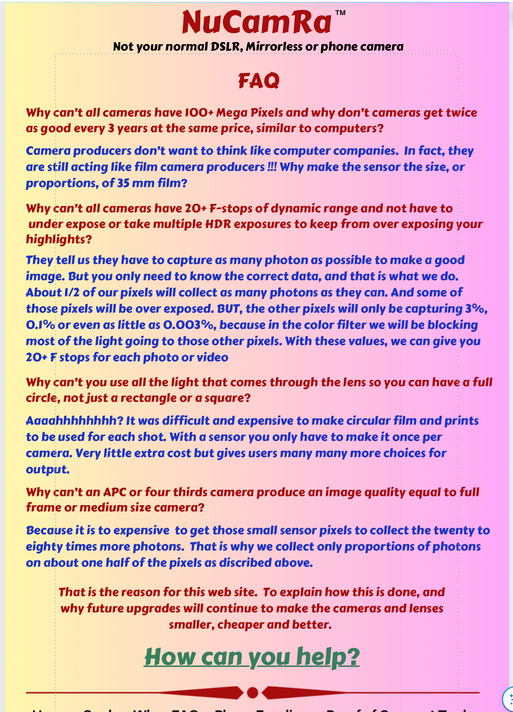
FAQ
Why can’t all cameras have 100+ Mega Pixels and why don’t cameras get twice as good every 3 years at the same price, similar to computers?
Camera producers don’t want to think like computer companies. In fact, they are still acting like film camera producers !!! Why make the sensor the size, or proportions, of 35 mm film?
Why can’t all cameras have 20+ F-stops of dynamic range and not have to under expose or take multiple HDR exposures to keep from over exposing your highlights?
They tell us they have to capture as many photon as possible to make a good image. But you only need to know the correct data, and that is what we do. About 1/2 of our pixels will collect as many photons as they can. And some of those pixels will be over exposed. BUT, the other pixels will only be capturing 3%, 0.1% or even as little as 0.003%, because in the color filter we will be blocking most of the light going to those other pixels. With these values, we can give you 20+ F stops for each photo or video
Why can’t you use all the light that comes through the lens so you can have a full circle, not just a rectangle or a square?
Aaaahhhhhhhh? It was difficult and expensive to make circular film and prints to be used for each shot. With a sensor you only have to make it once per camera. Very little extra cost but gives users many many more choices for output.
Why can’t an APC or four thirds camera produce an image quality equal to full frame or medium size camera?
Because it is to expensive to get those small sensor pixels to collect the twenty to eighty times more photons. That is why we collect only proportions of photons on about one half of the pixels as discribed above.
That is the reason for this web site. To explain how this is done, and why future upgrades will continue to make the cameras and lenses smaller, cheaper and better.
NuCamRa
TM
Not your normal DSLR, Mirrorless or phone camera
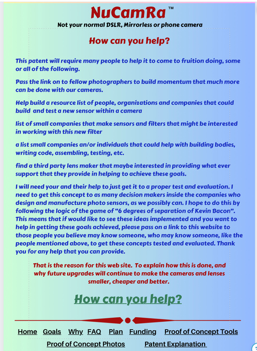
How can you help?
This patent will require many people to help it to come to fruition doing, some or all of the following.
Pass the link on to fellow photographers to build momentum that much more can be done with our cameras.
Help build a resource list of people, organizations and companies that could
build and test a new sensor within a camera
list of small companies that make sensors and filters that might be interested in working with this new filter
a list small companies an/or individuals that could help with building bodies, writing code, assembling, testing, etc.
find a third party lens maker that maybe interested in providing what ever support that they provide in helping to achieve these goals.
I will need your and their help to just get it to a proper test and evaluation. I need to get this concept to as many decision makers inside the companies who design and manufacture photo sensors, as we possibly can. I hope to do this by following the logic of the game of “6 degrees of separation of Kevin Bacon”. This means that if would like to see these ideas implemented and you want to help in getting these goals achieved, please pass on a link to this website to those people you believe may know someone, who may know someone, like the people mentioned above, to get these concepts tested and evaluated. Thank you for any help that you can provide.
That is the reason for this web site. To explain how this is done, and why future upgrades will continue to make the cameras and lenses smaller, cheaper and better.
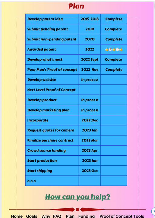
Plan
Develop patent idea | 2015-2018 | Complete |
Submit pending patent | 2019 | Complete |
Submit non-pending patent | 2020 | Complete |
Awarded patent | 2022 | 👍🎂👍🎂👍 |
Develop what’s next | 2022 Sept | Complete |
Poor Man’s Proof of concept | 2022 Nov | Complete |
Develop website | In process | |
Next Level Proof of Concept | ||
Develop product | In process | |
Develop marketing plan | In process | |
Incorporate | 2022 Dec | |
Request quotes for camera | 2023 Jan | |
Finalize purchase contract | 2023 Mar | |
Crowd source funding | 2023 Apr | |
Start production | 2023 Jun | |
Start shipping | 2023 Oct | |
o o o |
Funding
To be Decided
Crowd sourcing, i.e. Kickstarter.
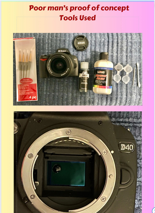
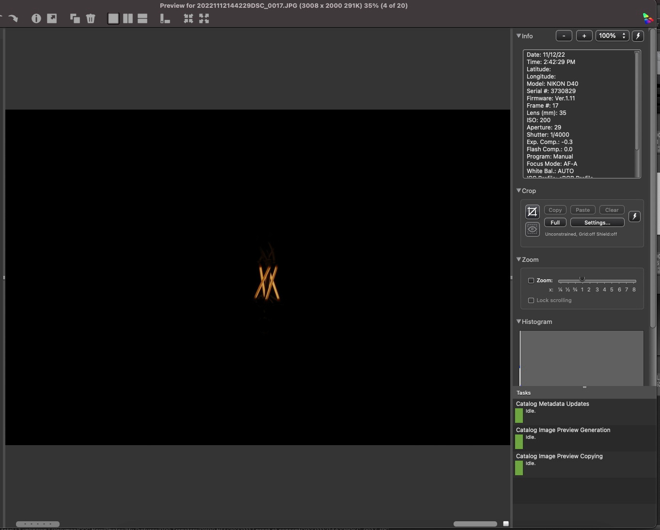
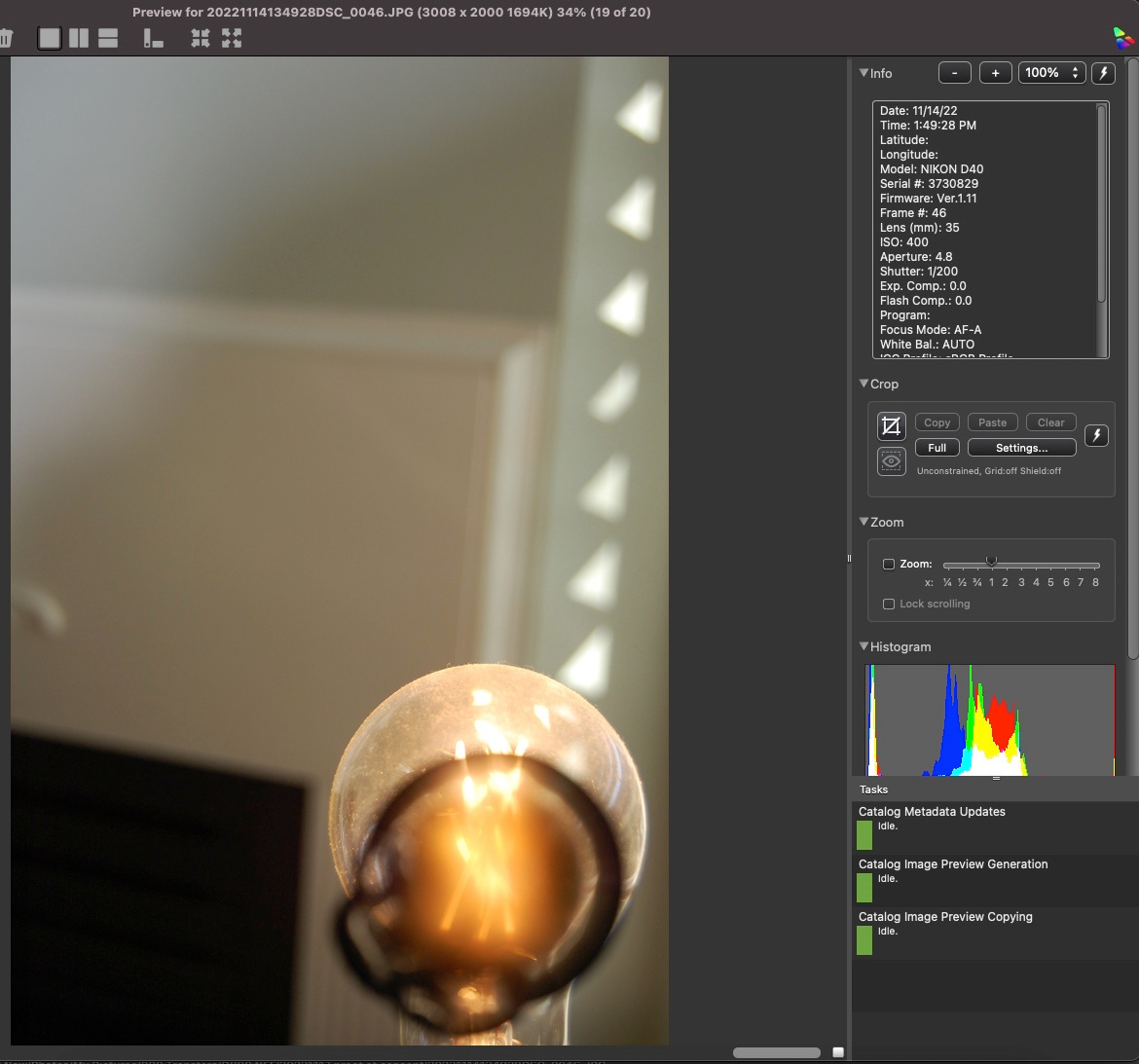
Poor man’s proof of concept
Tools Used
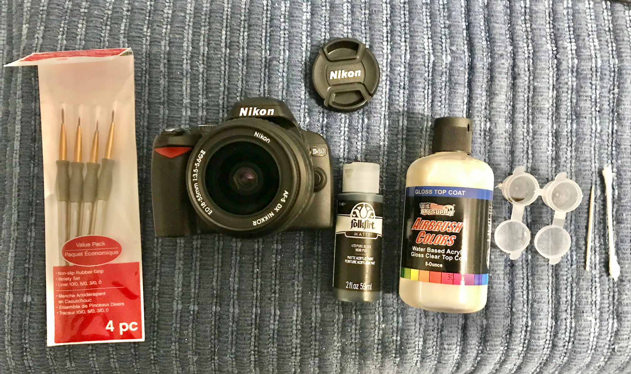
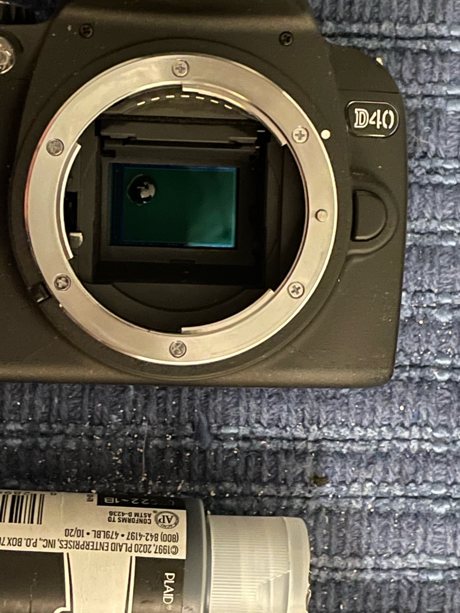
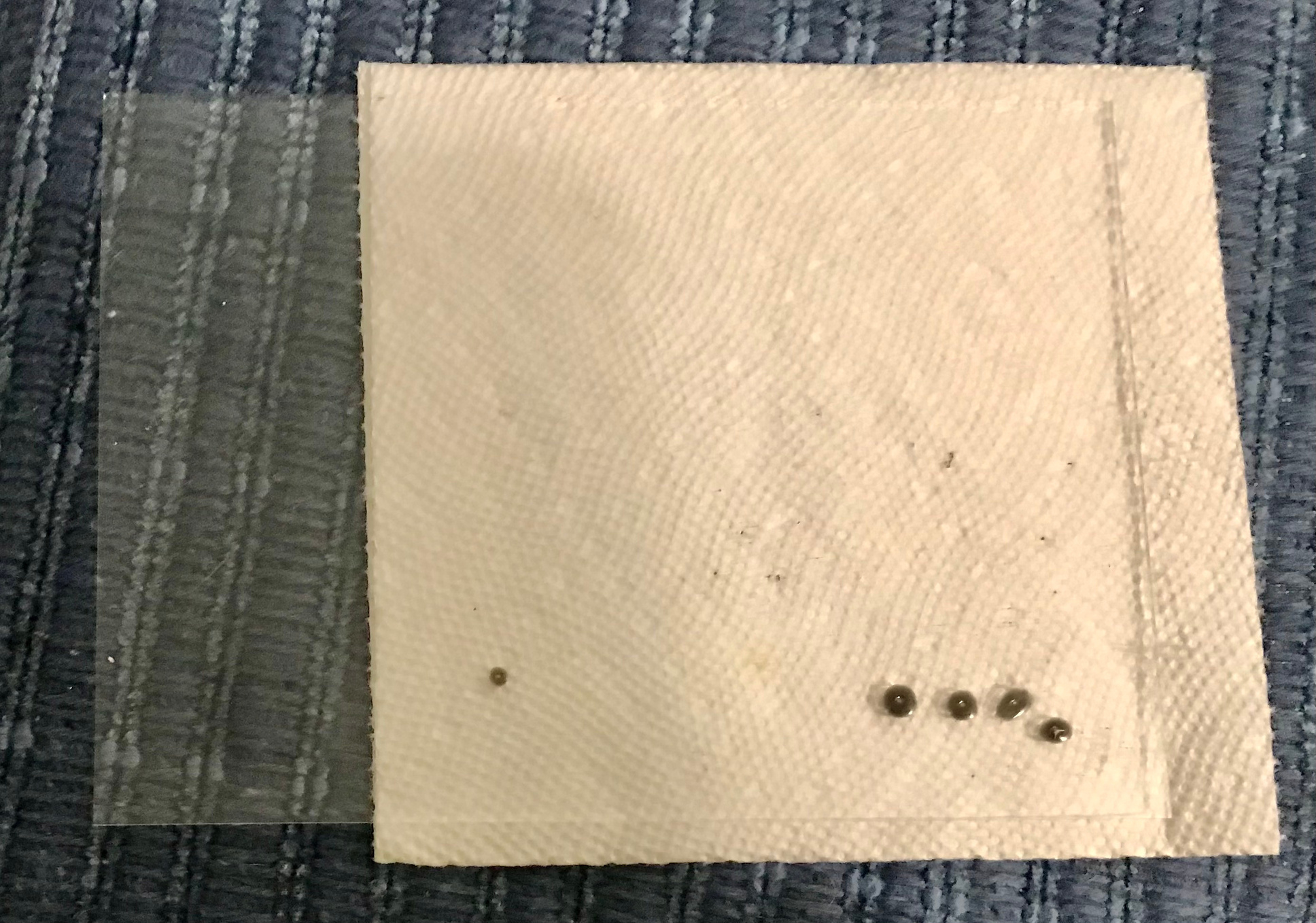
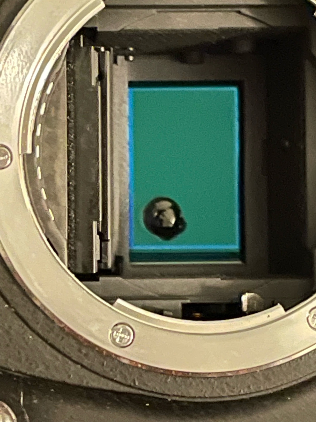
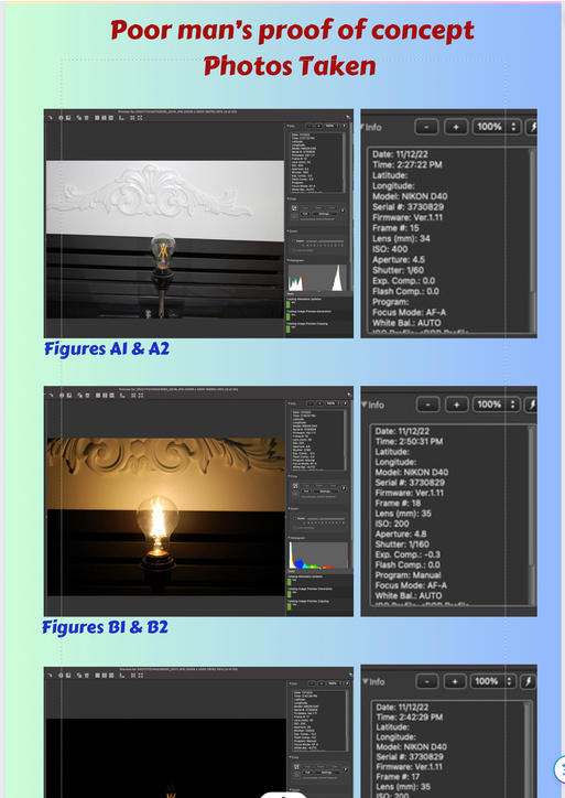
Poor man’s proof of concept
Photos Taken

Figures A1 & A2

Figures B1 & B2
Figures C1 & C2
Figures D1 & D2

Figures E1 & E2
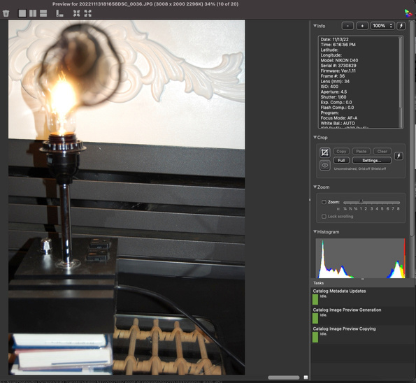
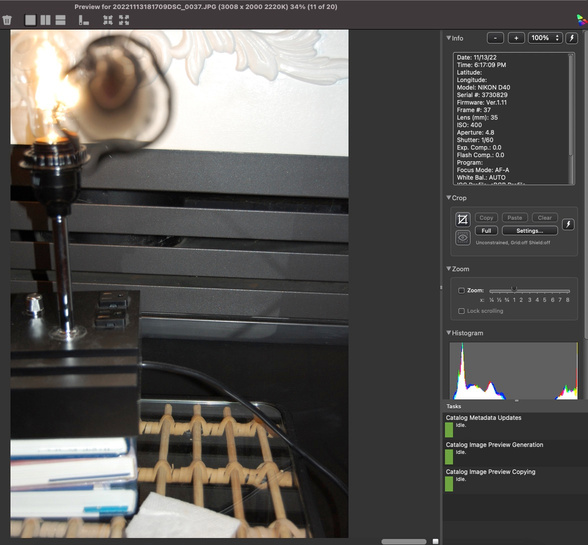
Figure | ISO | Aperture | Shutter | ||
Figures A | 400 | 4.5 | 1/60 | ||
Figures B | 300 | 4.8 | 1/60 | ||
Figures C | 200 | 29 | 1/4000 | ||
Figures D | 400 | 4.8 | 1/200 | ||
Figures E | 320 | 5.6 | 1/500 | ||
C & D difference | 1 f-stop | 2.5 f-stop | 4+ f-stops | = | 7.5 f stops |
Patent Explanation
Electronic Imaging Enhancement System
Patent #11240451 granted February 1, 2022
No more catching as many photons as possible
Now catch proportions of photons
100% here, 3% there, 0.1% over there and 0.003% up there
Introduction
This patent introduces a new filter which changes the way a camera’s sensor/pixel design manages photons. The current filter used in today’s digital cameras passes photons through a color filter (red/green/blue) to the sensor/pixel design which stores them in the corresponding pixel. The pixel is a 2X2 repeating pattern of accumulated color photons of red, green, blue, green (RGBG). The receiving pixel has a maximum number of photons it can store. Therefore, when the number of photons exceeds that limit the number received beyond that limit will not be used in calculating the color. This is one of the limitations of digital imaging versus color film. The other is the cost to research, develop and manufacture the pixels to capture as many photons in the smallest space possible. Thus the pixel is designed in a cost verses capability environment.
This patent designs a new filter that changes storage in the pixel by adding clear and dark components, like a neutral density filter, to the color filter. The filter processes the photons proportionately using red, green, blue, clear and dark (RGBCD). The key to the new filter is being able to manage the problem of pixels reaching their maximum storage and therefore not counting all photons and losing that color data. This patent addresses this problem in a counter intuitive way - by decreasing the maximum number of photons a pixel can accumulate This patent’s solution is to add several levels of neutral density type photon blocking material to the filter. These neutral densities vary in value of the percentage of photons being blocked from passing through the filter i.e., 97%, 99.1%, 99.999%. This blocking component will be applied to 25% to 65 % of the pixels. Knowing the number of photons that have made it through the neutral density components, and the percentage of the blocking power of that component, determines the quantities of photons trying to reach the pixels. Thus, calculated photons quantities per pixel can be up to an order of several magnitudes greater than the pixel limit. This is imitating an analog film via a digital device.
Using the new filter with existing sensor/pixel design size:
- You can more than double the number of pixels on the new sensor/pixel design in each of the first three generations
- Reduce the sensitivity to photons at each pixel, ie. lower the maximum number of photons collected
- Replace one of the repeating green filters with a clear filter
- Replace second green filter with a component that blocks more than two/thirds of the photons from reaching the new sensor/pixel design
- Reduce R&D on improving photon capture while maintaining it for speed in reading pixel values
- Establish baseline for future generations i.e, as pixels get smaller add additional colors to the color filter, starting by returning the green filter.
Results
1. Significantly enhances Resolution
2. Significantly enhances Color Quality
3. Reduces Cost
Using the new filter with reduced size sensor/pixel design:
- Reduce the sensor/pixel design size by 50% and double the number of pixels
- Significantly reduce the sizes of the camera body and lenses
- Repeat items 2 thru 6 from above
Results
1.Significantly reduces overall size
2.Significantly enhances Resolution
3.Enhances Color Quality
4.Significantly Reduces Cost
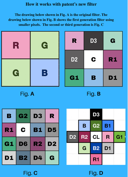
How it works with patent’s new filter
The drawing below shown in Fig. A is the original filter. The drawing below shown in Fig. B shows the first generation filter using smaller pixels. The second and third generations are Fig. C & D, and Fig. E is for a first generation monochrome filter. For info on how to create the neutral density effect at the pixel level, as well as many other color layouts, visit the US Patent #11240451.

Fig. A
R | D3 | G |
D2 | C | R1 |
G1 | B | D1 |
Fig. B
B | G2 | D3 | R |
R1 | C | B1 | D5 |
G1 | D6 | R2 | D2 |
D1 | B2 | D4 | G |
Fig. C
Fig. D
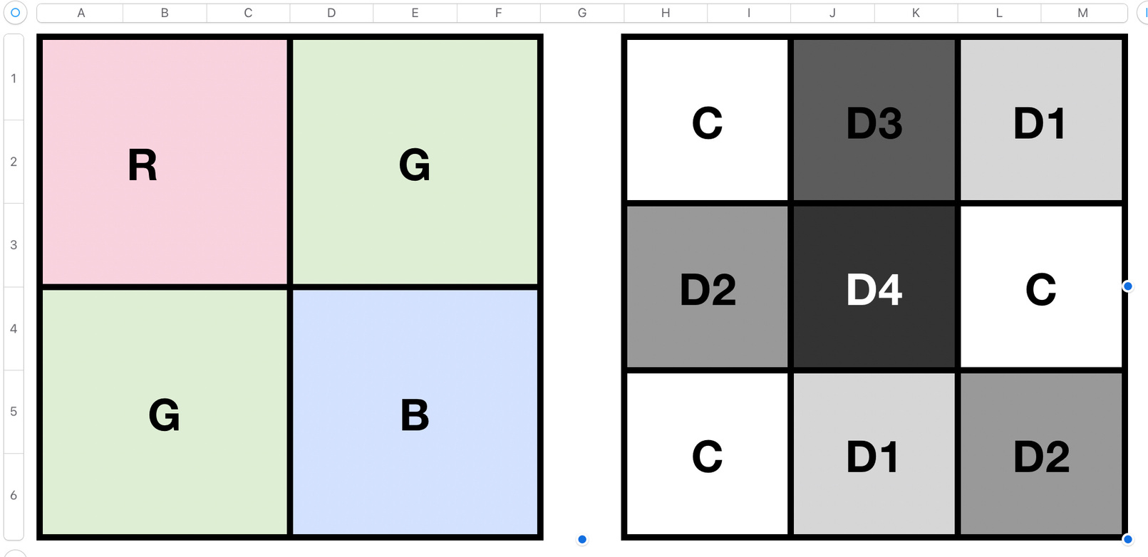
Fig. E
R | D3 | G |
D2 | C | R1 |
G1 | B | D1 |
Fig. A
Fig. B
Following are the differences between the old repeating pattern of the color filter and the first generation of the new aggressive repeating design.
- The first generation (Fig. B) has 9 pixels in the same space then the original design(Fig. A) with 4 pixels thus greater resolution
- If the original sensor/pixel design had 1,000 pixels, the same size newly redesigned sensor/pixel design will have 2,250 pixels - a 225% increase in pixels
- If you reduced the original sensor/pixel design by 50% it would have 500 pixels while the new smaller pixels on the reduced sensor/pixel design would be 1125. Still over 12% more than the original sensor/pixel design had. This means that the reduced sensor/pixel designs resolution is still more than 12% greater than the original sensor/pixel design with the large pixels and larger sensor
- On the new smaller pixels there is also a red, green, and blue filter. But since the pixels are smaller these will fill up to the maximum quantity of photons much more often. This is why there are a second set of red and green. The R1 and G1 will have a blocking agent that limits 67% of the photons from reaching the pixels. There is also a clear transparent filter, which is used for low light collection. Finally the are 3 more clear filters that have blocking agents with 67, 99.5 and 99.95% values.
- If the new RGB and Clear photon levels do not max out, they will be used calculate the color value for that one pixel marked C. If 1 or more RGB or Clear pixels are maximized, then the appropriate R1, G1 or D1 will also be used calculate the color value. If one of these x1 values are maximized, the the appropriate R2, G2 or D2 will also be used calculate the color value. Finally, if D2 is maximized, then D3 will also be used calculate the color value.
- For reference, the value calculated in ‘e’ is for the pixel marked C. To calculate the next pixel the pattern will shift 1 pixel to the right, and that value will be for the pixel currently makes R1. And so on across the row. At the end of the row the pattern will drop down 1 pixel and start again from the left hand side.
Fig. A
B | G2 | D3 | R |
R1 | C | B1 | D5 |
G1 | D6 | R2 | D2 |
D1 | B2 | D4 | G |
Fig. C
Following are the differences between the old repeating pattern of the color filter and the second generation of the new aggressive repeating design.
- The second generation(Fig. C) has 16 pixels in the same space then the original design(Fig. A) with 4 pixels thus greater resolution
- If the original sensor/pixel design had 1,000 pixels, the same size newly redesigned sensor/pixel design will have 4000 pixels - a 400% increase in pixels
- If you reduced the original sensor/pixel design by 50% it would have 500 pixels while the new smaller pixels on the reduced sensor/pixel design would be 2000. Still 200% more than the original sensor/pixel design had. This means that the reduced sensor/pixel designs resolution is still 200% greater than the original sensor/pixel design with the large pixels and sensor
- On the new smaller pixels there is also a red, green, and blue filter. But since the pixels are smaller these will fill up to the maximum quantity of photons much more often. This is why there are 2 more sets of red, green, and blue. The R1, G1 and B1 will have a blocking agent that limits 67% of the photons from reaching the pixels. The R2, G2 and B2 will have a blocking agent that limits 99.5% of the photons from reaching the pixels. There is also a clear transparent filter, which is used for low light collection. Finally the are 3 more clear filters that have blocking agents with 67, 99.5 and 99.95% values.
- If the new RGB and Clear photon levels do not max out, they will be used calculate the color value for that one pixel marked CL. If 1 or more RGB or Clear pixels are maximized, then the appropriate R1, G1, B1 or D1 will also be used calculate the color value. If one of these x1 values are maximized, the the appropriate R2, G2, B2 or D2 will also be used calculate the color value. Finally, if D2 is maximized, then D3 will also be used calculate the color value.
Fig. A
Fig. D
Following are the differences between the old repeating pattern of the color filter and the first generation of the new aggressive repeating design.
- The third generation (Fig. D) has 25 pixels in the same space then the original design(Fig. A) with 4 pixels thus greater resolution
- If the original sensor/pixel design had 1,000 pixels, the same size newly redesigned sensor/pixel design will have 6,250 pixels - a 626% increase in pixels
- If you reduced the original sensor/pixel design by 50% it would have 500 pixels while the new smaller pixels on the reduced sensor/pixel design would be 3,125. Still over 300% more than the original sensor/pixel design had. This means that the reduced sensor/pixel designs resolution is still more than 300% greater than the original sensor/pixel design with the large pixels and sensor
- On the new smaller pixels there is also a red, green, and blue filter. But since the pixels are smaller these will fill up to the maximum quantity of photons much more often. This is why there are 2 more sets of red, green, and blue. The R1, G1 and B1 will have a blocking agent that limits 67% of the photons from reaching the pixels. The R2, G2 and B2 will have a blocking agent that limits 99.5% of the photons from reaching the pixels. There is also a clear transparent filter, which is used for low light collection. Finally the are 3 more clear filters that have blocking agents with 67, 99.5 and 99.95% values.
- If the new RGB and Clear photon levels do not max out, they will be used calculate the color value for that one pixel marked CL. If 1 or more RGB or Clear pixels are maximized, then the appropriate R1, G1, B1 or D1 will also be used calculate the color value. If one of these x1 values are maximized, the the appropriate R2, G2, B2 or D2 will also be used calculate the color value. Finally, if D2 is maximized, then D3 will also be used calculate the color value.
- For reference, the value calculated in ‘e’ is for the pixel marked CL. To calculate the next pixel the pattern will shift 1 pixel to the right, and that value will be for the pixel currently makes R. And so on across the row. At the end of the row the pattern will drop down 1 pixel and start again from the left hand side
Fig. A
Fig. E
Following are the differences between the old repeating pattern of the color filter and the first generation of the new aggressive repeating design.
- The first generation black and white has 9 pixels in the same space then the original design(Fig. A) with 4 pixels thus greater resolution
- If the original sensor/pixel design had 1,000 pixels, the same size newly redesigned sensor/pixel design will have 2,250 pixels - a 225% increase in pixels
- If you reduced the original sensor/pixel design by 50% it would have 500 pixels while the new smaller pixels on the reduced sensor/pixel design would be 1,125. Still over 12% more than the original sensor/pixel design had. This means that the reduced sensor/pixel designs resolution is still more than 300% greater than the original sensor/pixel design with the large pixels
- On the new smaller pixels there is also a red, green, and blue filter. But since the pixels are smaller these will fill up to the maximum quantity of photons much more often. This is why there are 2 more sets of red, green, and blue. The R1, G1 and B1 will have a blocking agent that limits 67% of the photons from reaching the pixels. The R2, G2 and B2 will have a blocking agent that limits 99.5% of the photons from reaching the pixels. There is also a clear transparent filter, which is used for low light collection. Finally the are 3 more clear filters that have blocking agents with 67, 99.5 and 99.95% values.
- If the new RGB and Clear photon levels do not max out, they will be used calculate the color value for that one pixel marked CL. If 1 or more RGB or Clear pixels are maximized, then the appropriate R1, G1, B1 or D1 will also be used calculate the color value. If one of these x1 values are maximized, the the appropriate R2, G2, B2 or D2 will also be used calculate the color value. Finally, if D2 is maximized, then D3 will also be used calculate the color value.
- For reference, the value calculated in ‘e’ is for the pixel marked D4. To calculate the next pixel the pattern will shift 1 pixel to the right, and that value will be for the pixel currently makes C. And so on across the row. At the end of the row the pattern will drop down 1 pixel and start again from the left hand side
Applying this patent aggressively will change the design, manufacturing and use of digital photo sensor/pixel designs thereby, achieving significantly greater resolution and quality while maintaining, either current sensor/pixel design size or the small sensor/pixel design size.
Glossary
Photons - electromagnetic radiation, i.e. visible light, infared, UV, x-rays, …
Color Filter (Bayer) - repeating pattern 2 green,1 red,1 blue in a 1:1 correlation to number of pixels, 1 pixel 1 color
Pixel - Detect and accumulate photons, which have a limited maximum storage for accumulating photons
Sensor/pixel design - Manages the information from all the pixels to produce an image and send it to storage
Image Quality - The more photons collected over all pixels will increase the image quality by showing the subtleties of brightness and color shading
Image Resolution - This is the image details, and the more pixels the more detail, thus greater resolution
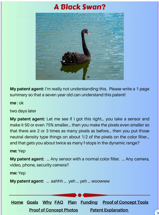
A Black Swan?
My patent agent: I’m really not understanding this. Please write a 1 page summary so that a seven year old can understand this patent!
me : ok
two days later
My patent agent: Let me see if I got this right… you take a sensor and make it 50 or even 75% smaller… then you make the pixels even smaller so that there are 2 or 3 times as many pixels as before… then you put those neutral density type things on about 1/2 of the pixels on the color filter… and that gets you about twice as many f-stops in the dynamic range?
me: Yep
My patent agent: … Any sensor with a normal color filter. … Any camera, video, phone, security camera?
me: Yep
My patent agent: ... aahhh … yeh … yeh … woowww